“Illegal Radio” was a task from the Freestyle category of the first edition of Olympic CTF. We were given a 5759712-sample FLAC file named “OLYMPIC-CTF.FM - 133.37MHz - IQ_Data.”.
The first step was to load this file into GNU Radio, a free/libre signal analysis and (de)modulation tool. The name of the file suggested that it was a quadrature-encoded signal captured at 133.37 MHz, probably of an FM radio transmission. I started out by adding a WAV Source block, a float-to-complex block and a waterfall plot.
 |
| Basic waterfall plot rendering pipeline. |
 |
| Waterfall plot of source signal. |
Nothing too terribly interesting there. Well, let's try to feed that into a WBFM (wideband frequency modulation) decoder and see what we get out of that.
 |
| FM decoding pipeline. |
 |
| Decoded FM signal. |
Now we're talking! Let's compare this to a FM signal spectrum description from Wikipedia:
 |
| Traditional FM radio spectrum. |
We can clearly see that these match perfectly. We have mono at the baseband, a 19kHz pilot signal, stereo audio at 23-53kHz (DSB-SC at 38kHz == 2x 19kHz), and an R(B)DS signal at 57kHz (== 3x 19kHz).
The first thing to do was to decode the actual audio - maybe the flag is there? For mono audio, we can just apply a low-pass filter with a treshold of 15kHz. For stereo, however, we have to build a more complicated pipeline. First we bandpass the 19kHz pilot with some additional gain. We then take that pilot, and multiply it twice with the bandpassed stereo audio to get the demodulated stereo channel. Then, we add the mono audio with the stereo channel to get the resulting left channel, and we subtract them for the right channel.
 |
| Mono & really awful stereo decoding. |
Well, we got some interesting
chiptune out of that, but nothing that sounds like a flag. What's really left is the RDS band. If you're not familiar with FM radio, RDS is the data transmission system that delivers in-band notifications to your radio receiver, eg. displays program and station information.
After grabbing an RDS specification from 1998 (probably the worst specification I've ever laid my eyes on) I understood that the physical layer of RDS is a BPSK (binary phase-shift keying) bitstream at 1187.5 bits per second, which is then to be decoded differentially and broken up into 104-bit frames. Each PSK symbol (in this case, a bit, since we're dealing with binary PSK) is sent every 48 cycles of the 57 kHz subcarrier.
Since I wasn't able to get the built-in GNU Radio PSK decoder to work, I decided to export the RDS band into a file and decode it in a Python script. I decided to lowpass the RDS bitstream at 2.2kHz (thus getting only the modulated waveform at 1187.5 Hz, without the 57kHz carrier) and export it to a wave file.
 |
| Exporting the RDS waveform. |
 |
| Resulting waveform. I can see data! |
Now, since we're dealing with binary PSK, there are only two phase states we have to deal with: 0 degrees and 180 degrees. We were dealing with a pretty stable clock, so I decided that my Python script would just sample every 48th frame from the wave file and try to figure out whether we were in one phase shift or the other. This amounted to checking if the sample was larger than zero - if it was, we emitted a logical 1, otherwise we emitted a logical 0. While naive, this approached seemed to sample the waveform in a sufficiently stable manner. I fed this into a differential decoder (previous_sample XOR current_sample) and got a bitstream.
 |
| Decoding differential BPSK into a bitstream. |
Now, we'll need to somehow make sense of this data. As stated earlier, the RDS bitstream is a constrant stream of 104-bit frames. These frames are made out of four groups of 26 bits. Each group carries 16 bits of data and 10 bits of checksum (which also carries information on the group we're dealinjg with). The groups are called A, B, C( or C') and D respectively, and they need to be in this order for a frame to be valid. According to the specification, the only way to synchronize the bitstream to frame boundary is to keep trying until we get something that seems to checksum properly - what the hell..?
The checksum is a custom 10 bit CRC with polynomial 0x5B9 xored with a group identifier (a different identifier for group A to D). Additionally, there is a bunch of „syndromes” you can synchronize to, but I didn't bother understanding how that exactly works - you are somehow supposed to checksum all 26 bits of a group and watch for a bunch of checksums to appear. Instead what I did was to try to fill a 26-bit shift register with incoming bits, grab the upper 16 and treat them as data, and treat the lower 10 as the checksum. Then, I tried veryfying checksums with every possible group identifier until we got something that looked like a valid group. I then tried receiving four properly checked groups in order, one after the other. If that happened, then we got a fully valid frame, and we could feed that to a frame decoder. Crusty, but hey, it worked.
 |
| Frames, we have frames! |
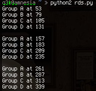
All that was left to do now was to parse frames. Each frame has 4 bits in group B that contain a frame type. All the frames I found in this stream were of type 2 - “RadioText”. Sounds promising! This type of frame carries four characters to be displayed at a certain offset on the 64-character display of a radio receiver. After some quit decoding, this is what we got:
 |
| Success! |


Great, Thanks !
ReplyDeleteNice bro!! I like it!
ReplyDeleteIt's easier with sdr-sharp ;) but well done .
ReplyDelete